|
BC-250 - Power Switch Wiring The Goal The goal is pretty simple. We just need the switch to bridge the power supply's "PS_ON" and "GND" pins so that the power supply turns on. And it needs to be a latching switch so that it stays bridged. A momentary switch won't work for this (at least not without extra wiring and transistors). Strategies Non-Modular Power Supply: If the power supply has a hard-wired ATX 24-pin connector, it's pretty straight-forward. If it's multi-colored, the single green wire is typically "PS_ON" and we can use any of the black wires for "GND". If the wires are all black (which is quite common), the pins are positioned in the same locations at the 24-pin connector. 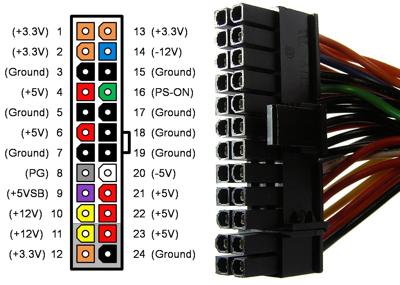 As long as the switch connects Pin 16 (PS_ON) to Pin 3, 5, 7, 15, 17, 18, 19 or 24 (GND), it'll work as intended. If you don't mind being a little destructive, you can snip the two wires we need and run them directly to the switch. There are also commonly-available adapters that bridge those pins. In the image below, the adapter on the left is an always-on bridge, while the one on the right is pre-attached to a switch, but with three wires (one powers an LED). 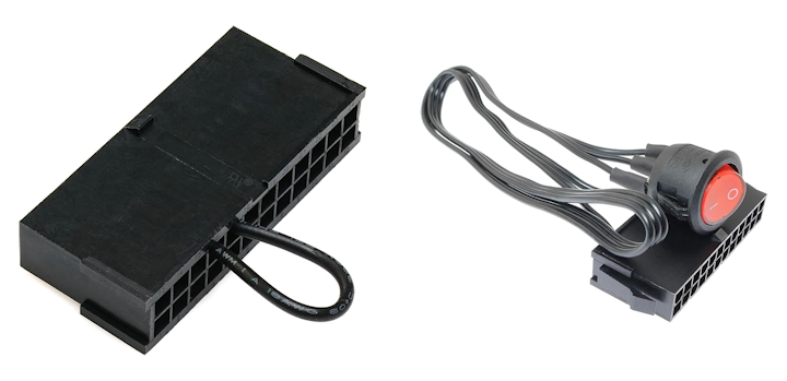 As displayed they don't quite fit our needs. The one on the left is always on, so it will constantly drain power, the fan will keep spinning, and it's not even connected to a switch, so we'd always need to use the power button on the rear of the BC-250 in order to turn it on. We could, however, cut the wire and extend it to our rocker switch with a little extra wire. For the switch on the right, we could disconnect or snip the wires and run the two that we need to the rocker switch. Alternatively, the front panel could be modified with a circular cutout to accommodate such a switch. The most annoying downside of any of the above strategies comes from having to stuff the entire 24-pin cable inside the case. One option would be to remove any unnecessary wires, but that increases the risk of something going wrong, and also removes the potential of using the power supply for another project in the future. Modular Power Supply: These are great for keeping the system tidy since we really only need the PCIE 6+2-pin cable to connect to the BC-250, plus two wires for the switch. 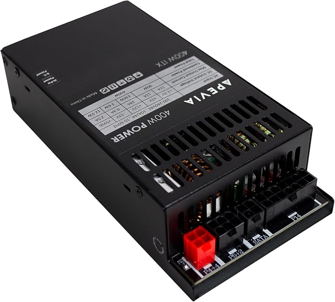 Where it gets a little more difficult is in determining which two pins on the 14-pin connector correspond to "PS_ON" and "GND", because different manufacturers use different pinouts. It's unsafe to assume that Pin X is always "PS_ON" and Pin Y is always "GND". Accidentally connecting a 12-volt pin with one that can't accept 12 volts, it could likely ruin the power supply. If you have a voltmeter, you can test the pins and wires to find the correct ones. You can also start with a pin at the 24-pin connector end of the cable and follow the wire back to the 14-pin connector. If you do this, I recommend doing it at least twice, just to be sure. At this point, you'll need to decide how you want to connect the switch to the power supply. You can create a custom wiring solution, or modify the 14-to-24-pin cable that comes with the power supply. 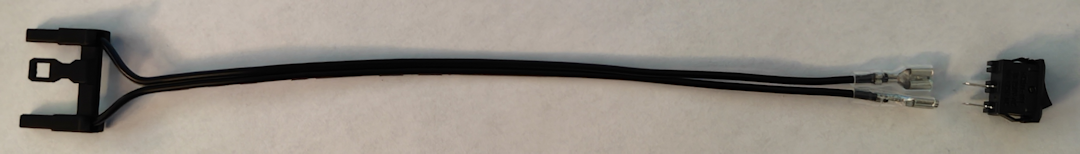 For even more power supply ideas, you can check out Old Lamer's Video, where he uses the LOP-300 module for an entirely custom solution. |
Copyright © 2026 Pocket Adventures.com