|
BC-250 - Case Assembly Parts List 3D-Printed Parts 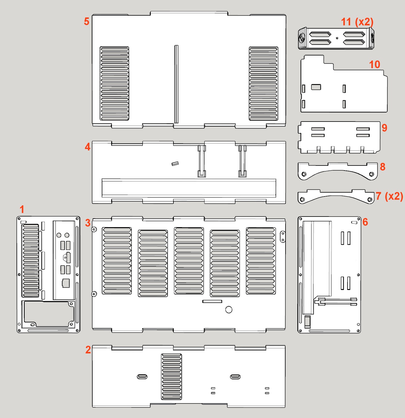
Hardware 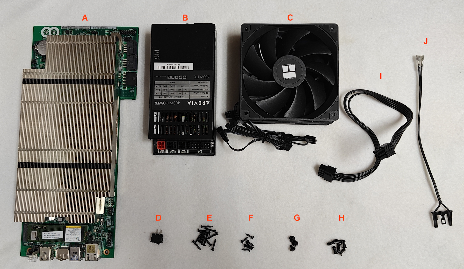
Tools 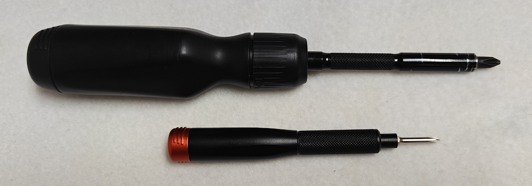 Standard Phillips-head screwdrivers used in PC-assembly. Assembly Instructions Step 1. Snap together the Bottom Panel (#2) and Right Panel (#3) starting at one end and working across. Take your time, as this it can take some careful alignment and a bit of force. Once together, the edge should act as a hinge with the two panels positioned at 90-degrees. 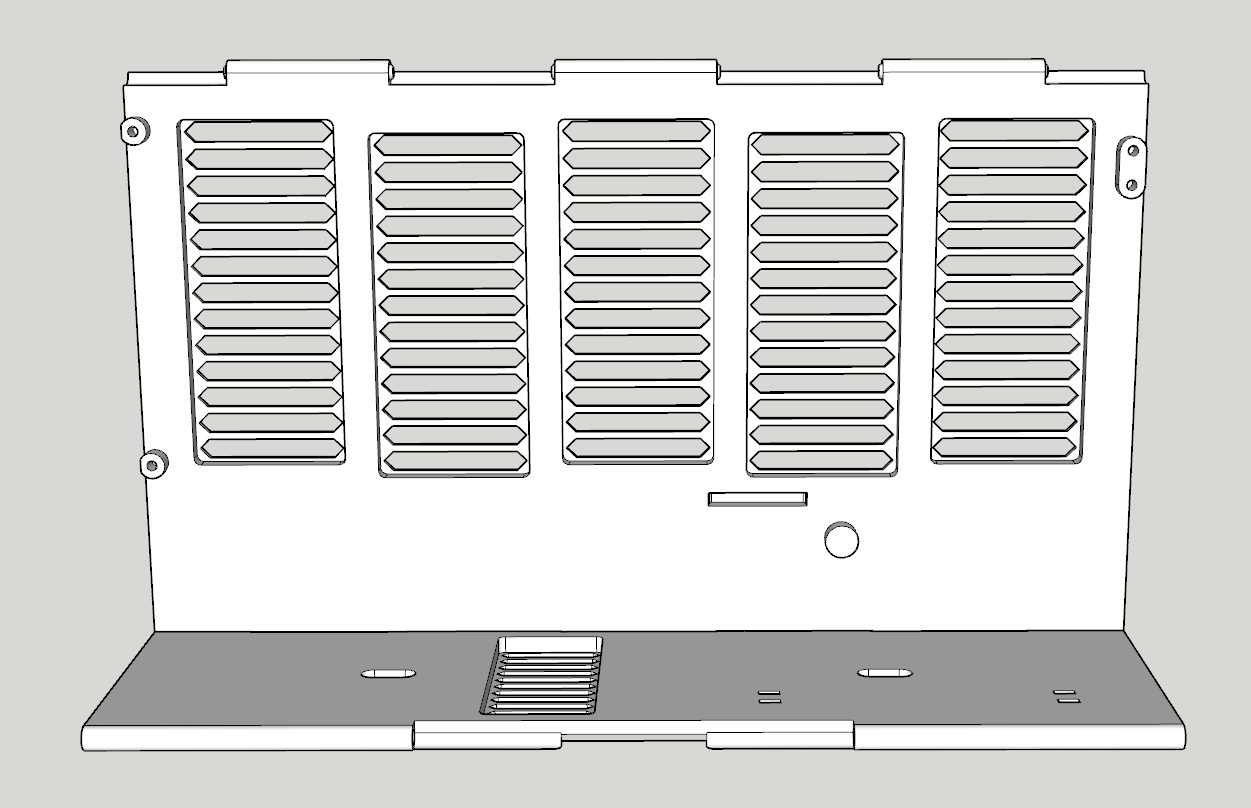 Step 2. Attach the Rear Panel (#1) using THREE M3-16mm Self-tapping Countersunk Screws (E). Don't over-tighten the screws as they can strip the plastic. Only tighten until the heads of the screws are flush with the surface of the Rear Panel. 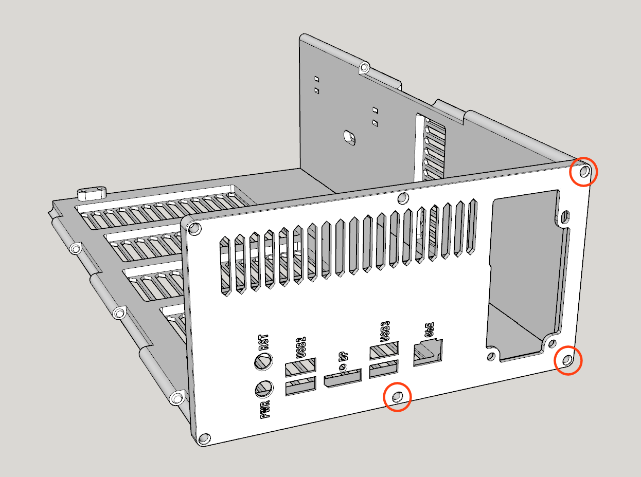 Step 3. Attach BOTH Feet (#11) to the Bottom Panel (#2) using TWOM3-10mm Self-tapping Pan Head Screws (F). Only tighten until the feet can barely slide from one side of the hole to the other. Leave them positioned toward the outer edge. 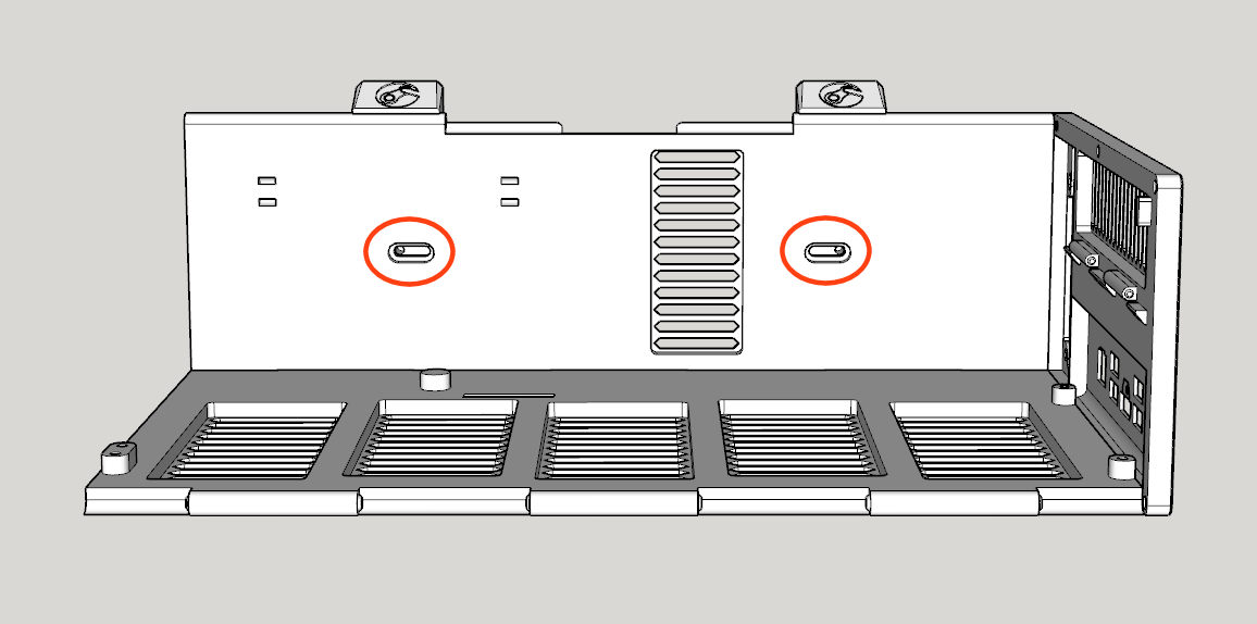 Step 4. Prepare and mount the Flex ATX Power Supply (B) to the Rear Panel (#1) using THREE #6-32 UNC Screws (G). If you have a modular power supply, attach the PCIE 6+2-pin Cable (I) and Power Switch Cable (J) first. Since power supplies vary, your wiring between the power supply and power switch can be different, but the intent of the switch is to bridge the PS_ON wire (typically the green wire on a 24-pin connector) with GND (black wire), which will start the power flowing into the BC-250 board. WARNING! Incorrect wiring can damage the power supply and BC-250, so please exercise caution and consult the Power Switch Wiring Guide for assistance. 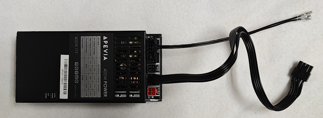 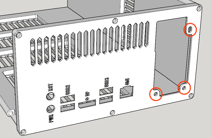 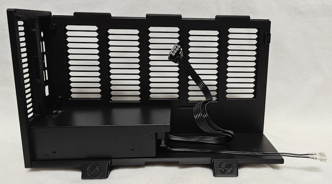 Step 5. Attach the PCIE 6+2-pin Cable (I) to the BC-250 (A), and then attach the BC-250 (A) to the Right Panel (#3) using FOUR M3-10mm Self-tapping Pan Head Screws (F) and to the Rear Panel (#1) using the tiny M2-3mm Countersunk Screw above the DisplayPort connector. 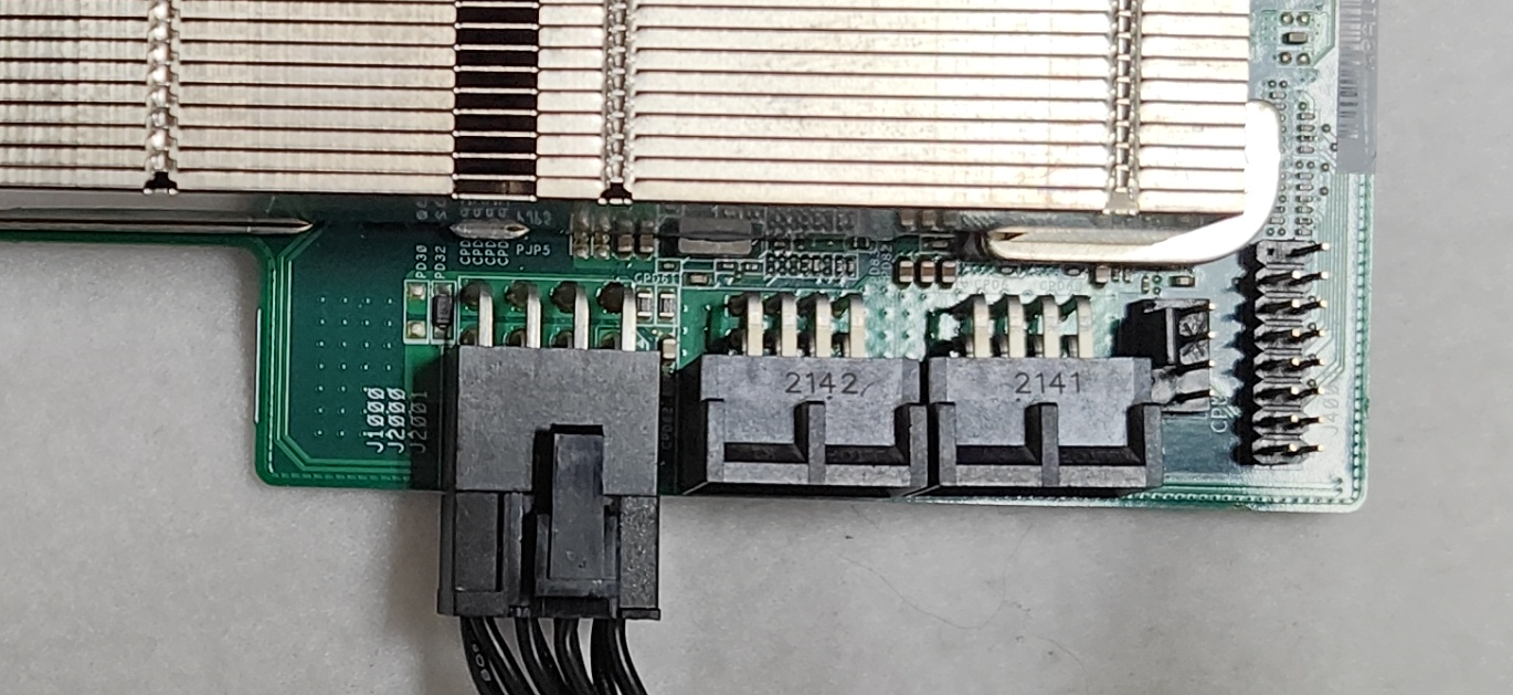 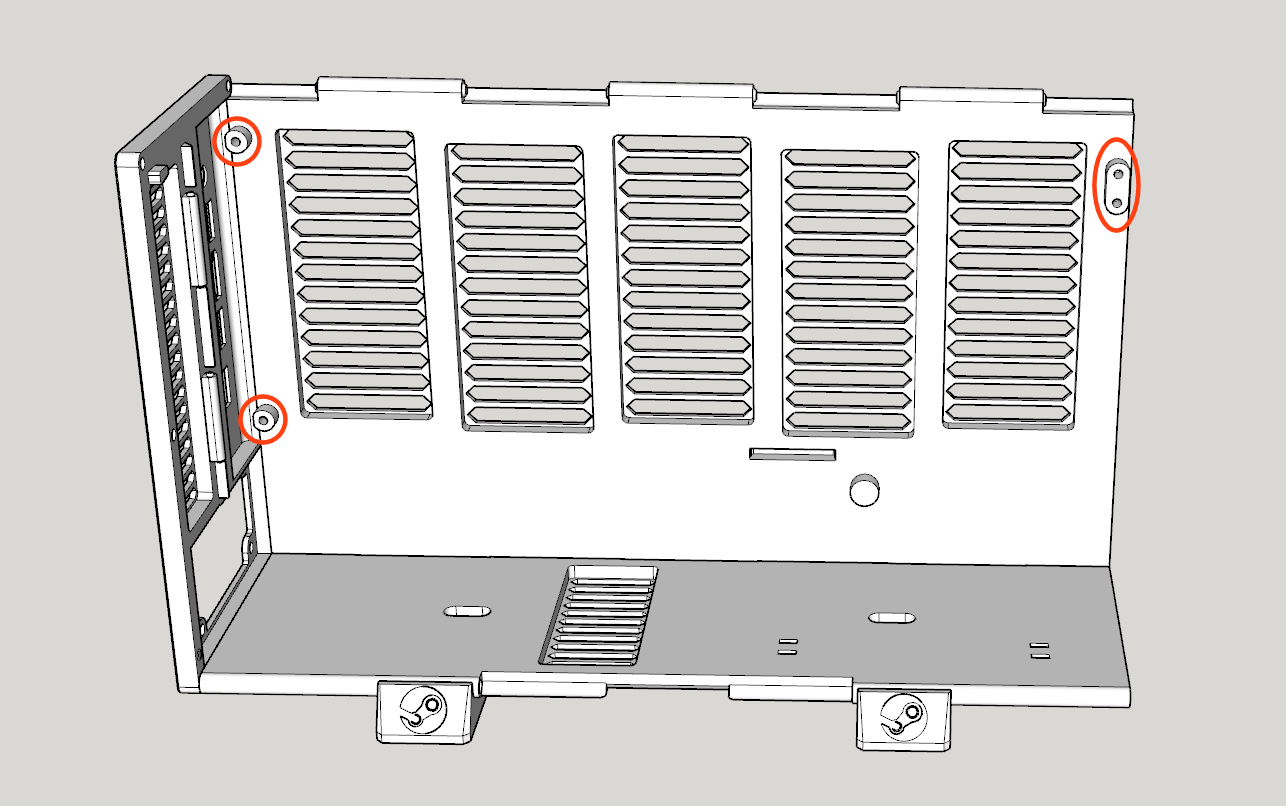 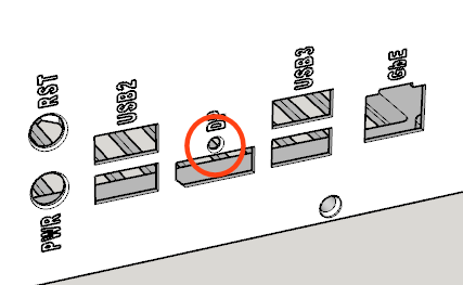 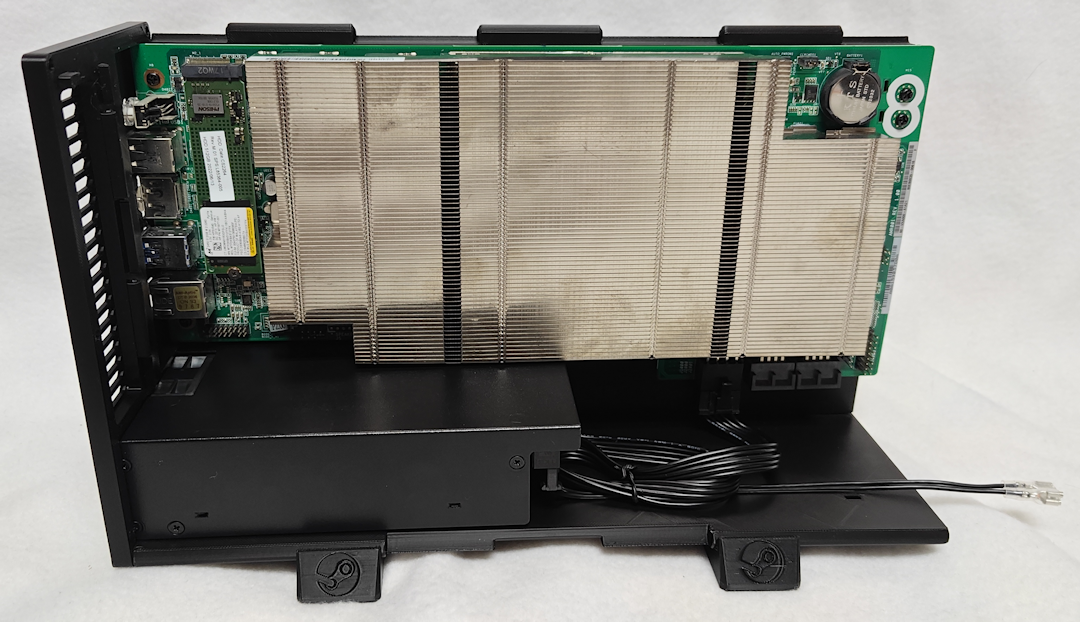 Step 6. Assemble the intake fan duct using Inner Duct Walls (#9, #10), ONE Intake Fan Mount (#7) and ONE 120mm Case Fan (C). Before securing the fan with TWO Self-tapping Fan Screws (H), route the fan's power cable through the rectangular hole in the Inner Duct Wall (Bottom). NOTE: The fan should be oriented so that it blows toward the BC-250. NOTE: The wider opening on the Fan Mount should face the nearest edge so that the heads of the Fan Screws sink below the surface when secured. 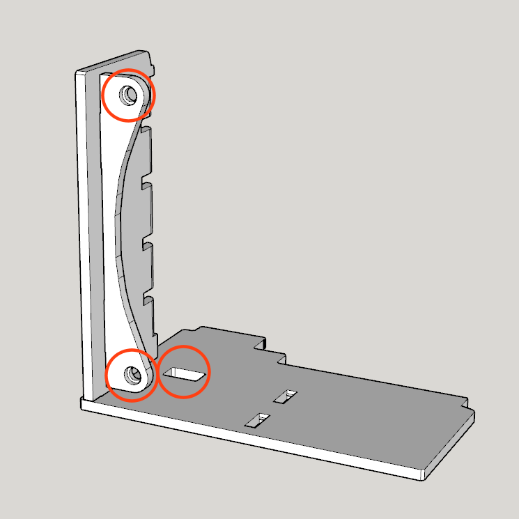 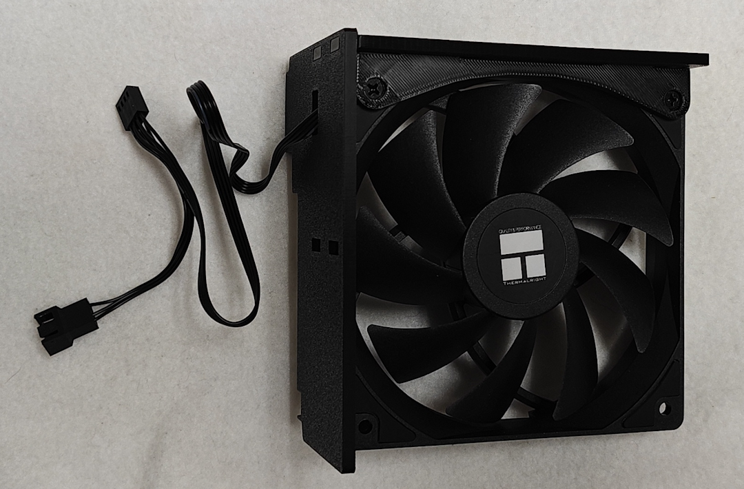 Step 7. Plug the Intake Fan (C)'s power connector into the BC-250 (A)'s fan header, and then attach the fan duct assembly using the slot toward the bottom of the Right Panel (#3). No screws are necessary for this step. NOTE: If using a fan splitter cable, connect that to the BC-250, and then connect the fan to the fan splitter cable. 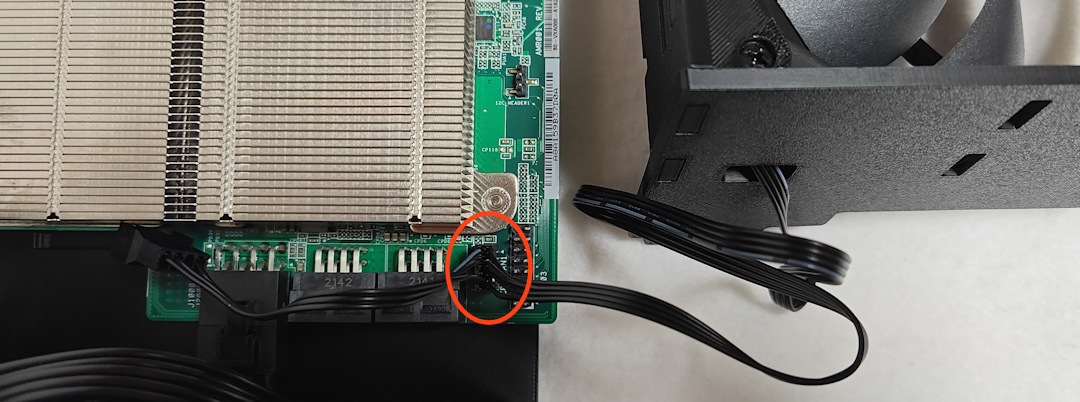 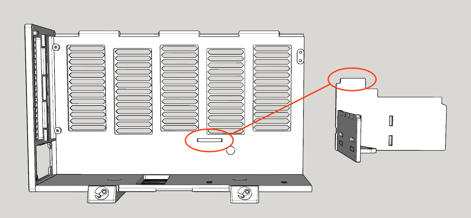 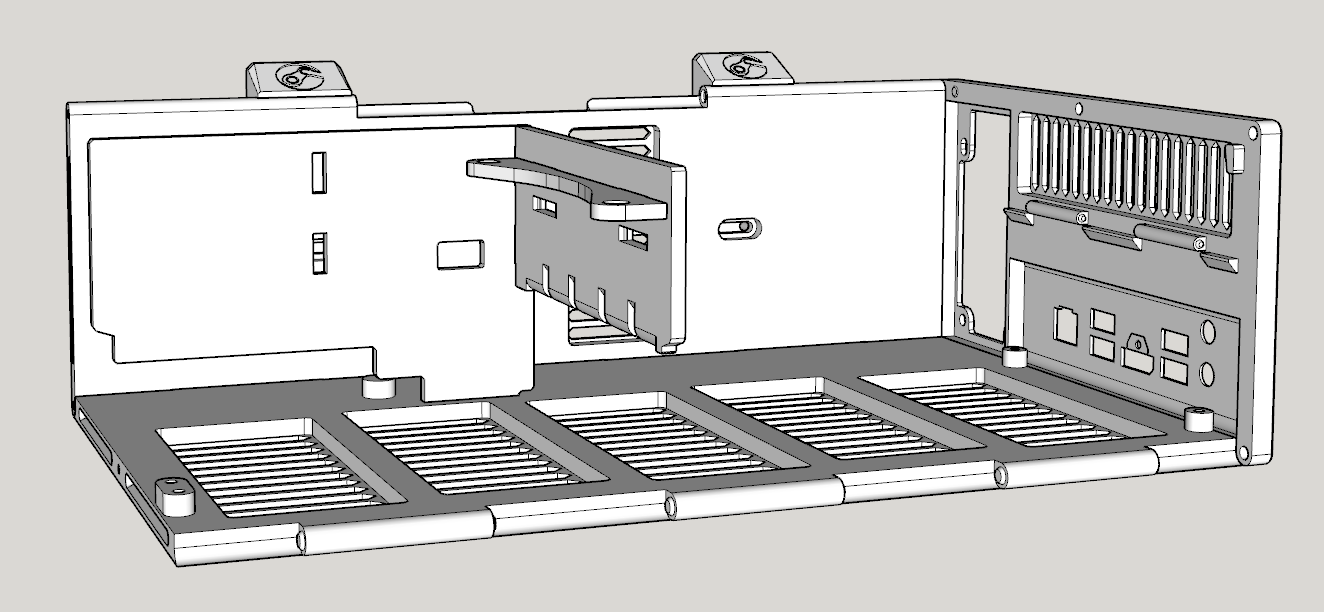 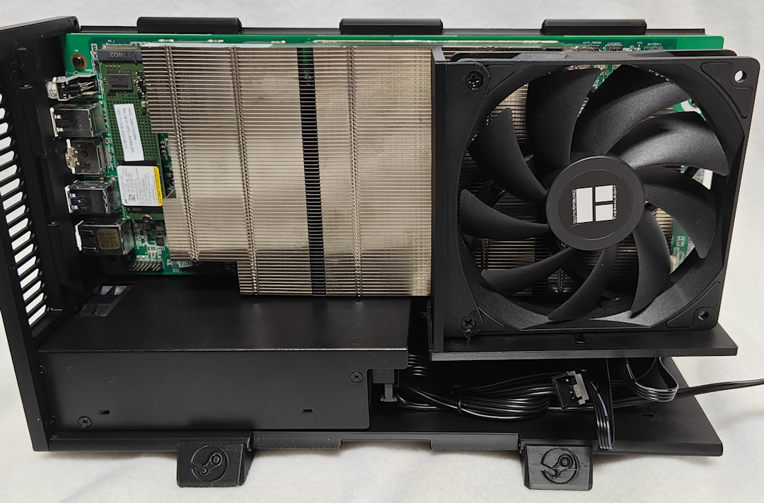 Step 8. Attach the final Intake Fan Mount (#7) to the Front Panel (#6) using the slots closest to the edge. Next, insert the Power Switch (D) through the front surface (below the Steam logo), so that the electrical contacts will be inside the case. It should snap into place with a little pressure. NOTE: The wider opening on the Fan Mount should face toward the nearest edge of the Front Panel so that the heads of the Fan Screws sink below the surface when secured (in the next step). 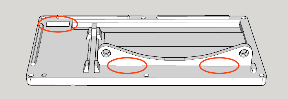 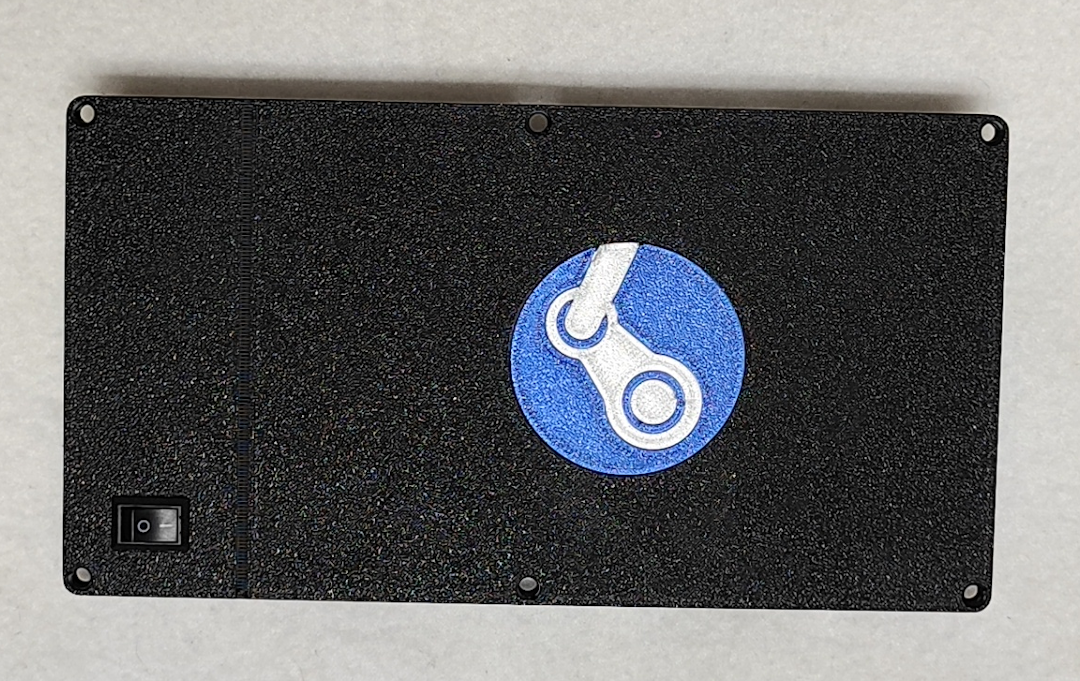 Step 9. Attach the Power Switch Cable (J) to the Power Switch (D). Next, attach the Front Panel (#6) using THREE M3-16mm Self-tapping Countersunk Screws (E). Then secure the Intake Fan to the Intake Fan Mount (#7) using TWO Self-tapping Fan Screws (H). 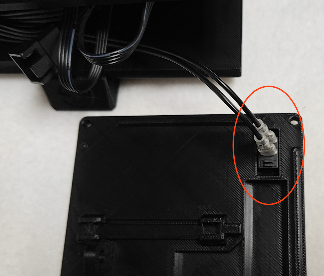 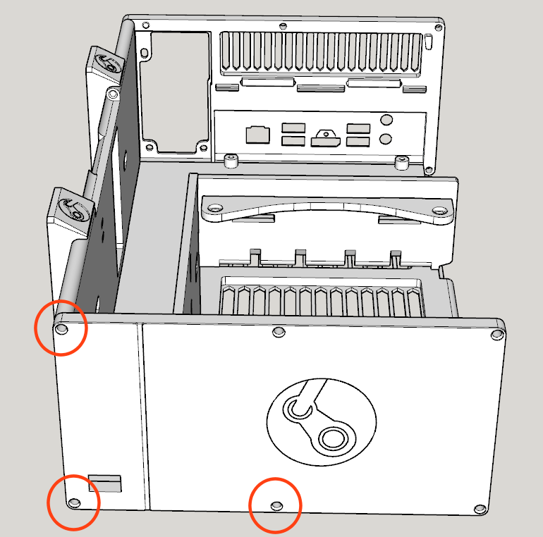 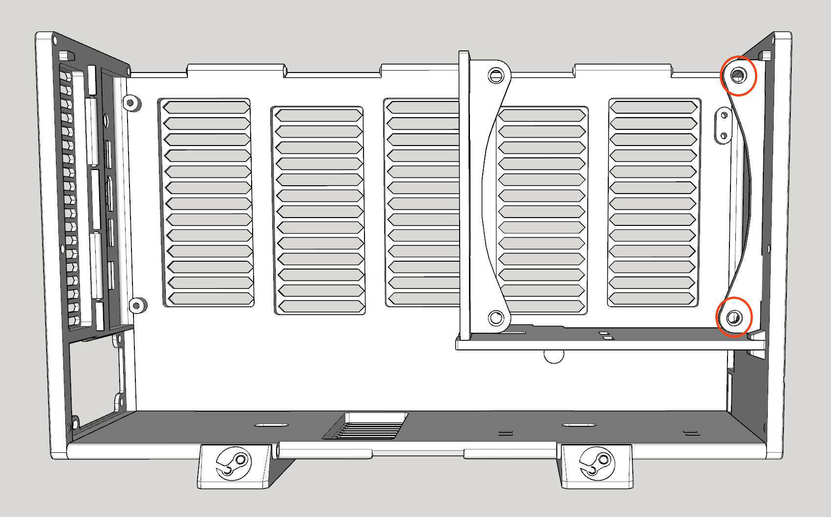 Step 10. Snap together the Top Panel (#4) to the Right Panel (#3). As with Step 1, this requires a bit of alignment and force, but if you start with one end and work toward the other, they should snap together fairly easily. Use FOUR M3-16mm Self-tapping Countersunk Screws (E) to secure the Top Panel (#4) in place. NOTE: If you're struggling with this step, it can help to secure the Top panel to the corners of the Front and Rear panels first (near the open Left side), which should give you the correct alignment and sufficient leverage to snap the Top and Right panels together. 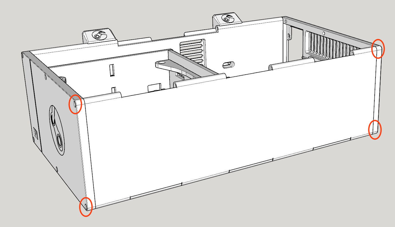 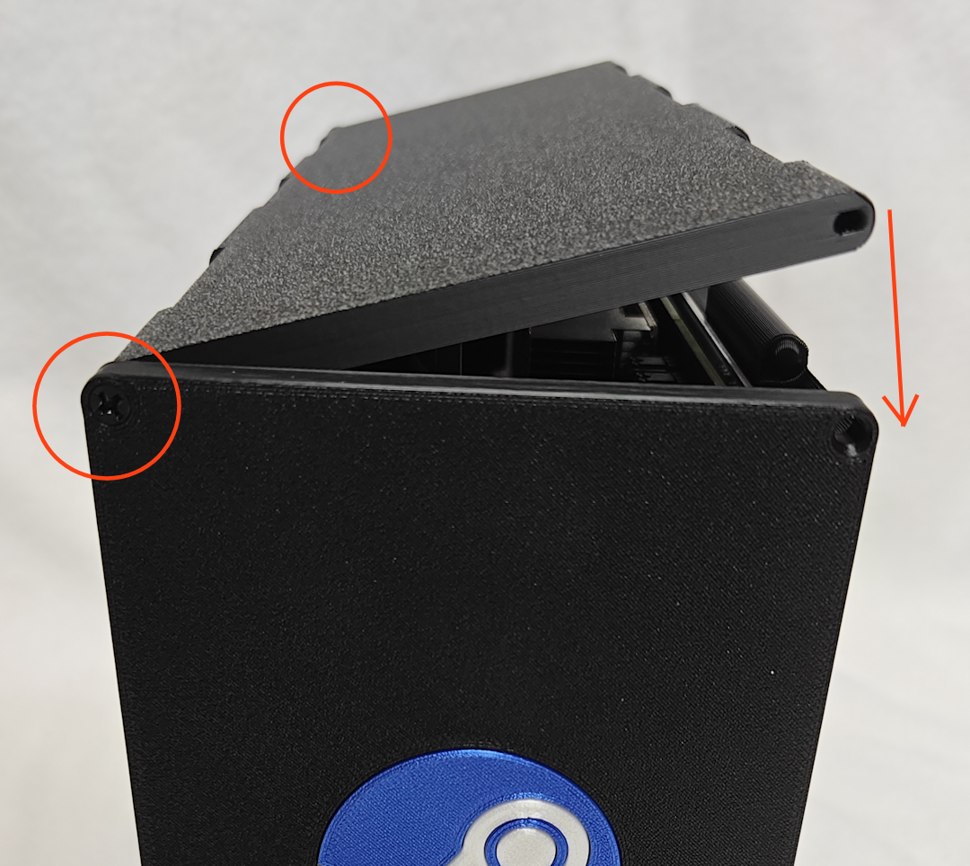 Step 11. Attach the Exhaust Fan Mount (#8) to the final 120mm Case Fan (C) using TWO Self-tapping Fan Screws (H). Next, attach the Exhaust Fan Mount (#8) to the Rear Panel (#1). Then connect the Exhaust Fan (C)'s power connector to the pigtail of the Intake Fan (C) (or fan splitter cable). NOTE: The fan should be able to swivel out of the way to provide access to the M.2 slot, and rest at an angle on the tiny shelf protruding from the Top panel. 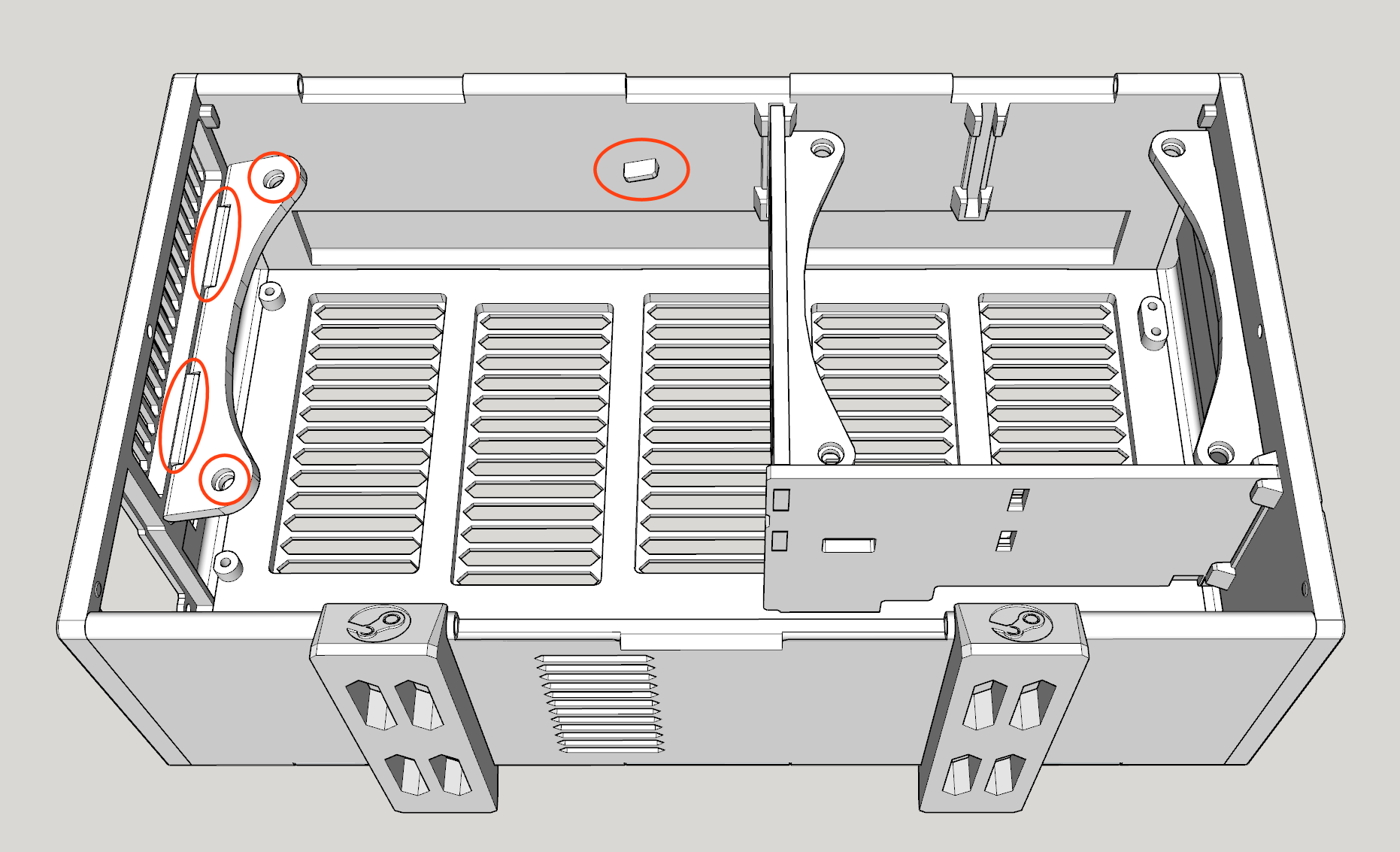 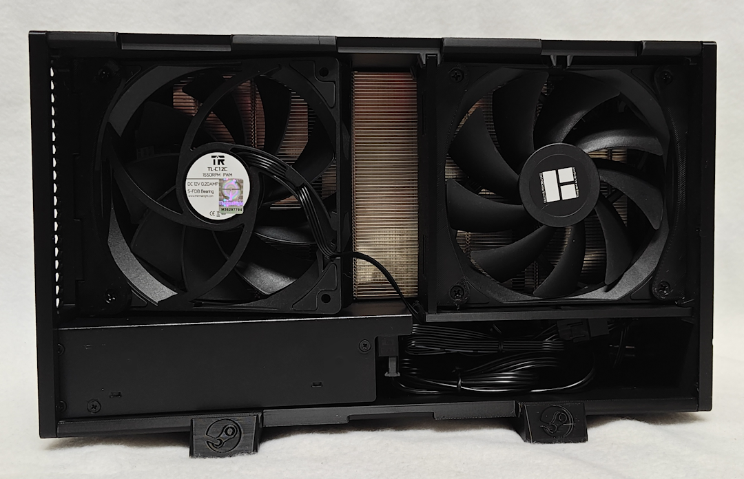 Step 12. Tuck all of the cables inside and snap together the Left Panel (#5) to the Top Panel (#4). As before, work from one side toward the other until it works as a hinge. Finally, secure the Left Panel (#5) to both the Front Panel (#6) and Rear Panel (#1) using the last TWO M3-16mm Self-tapping Countersunk Screws (E). Slide the Feet (#11) toward the center. 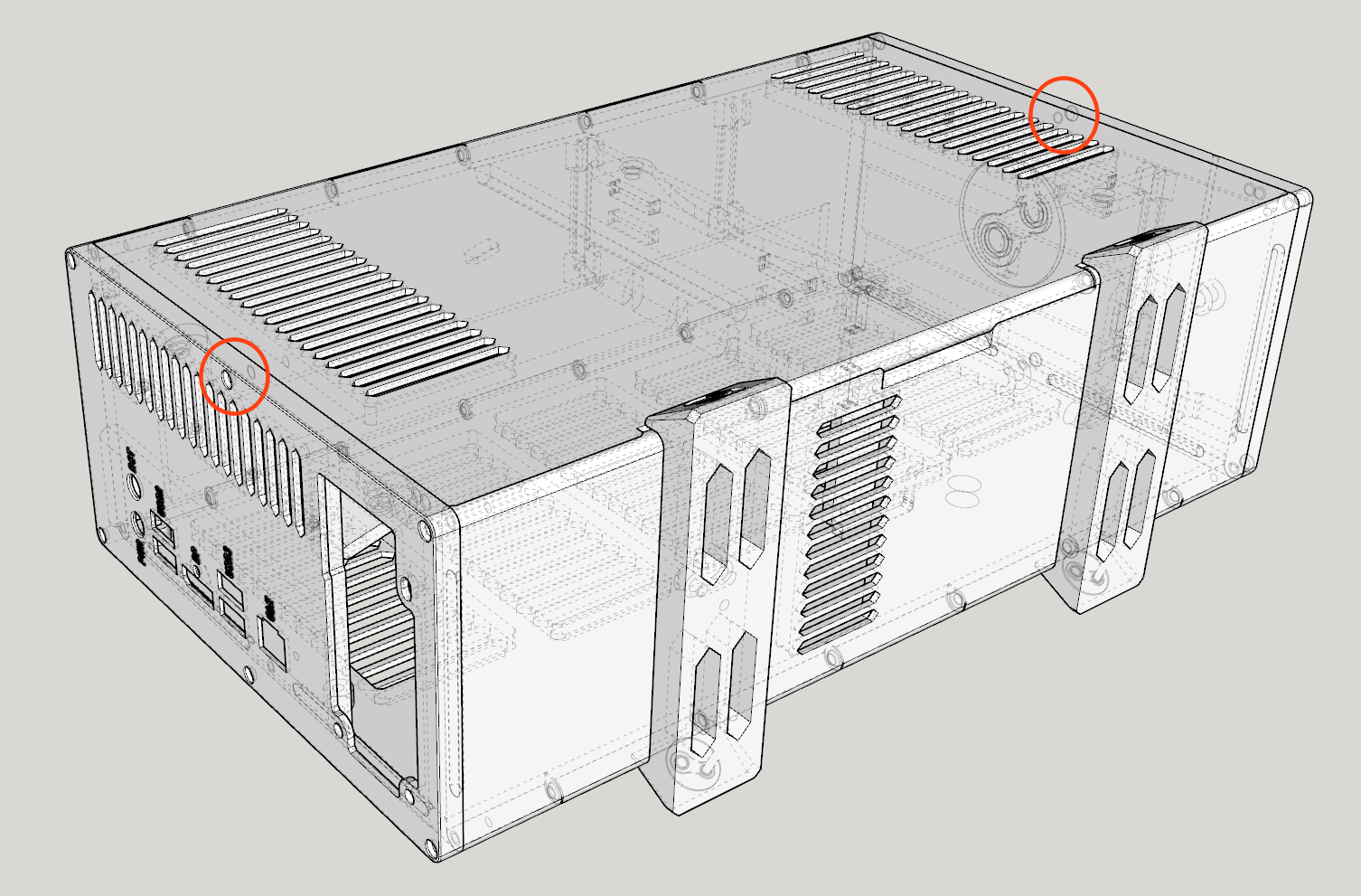 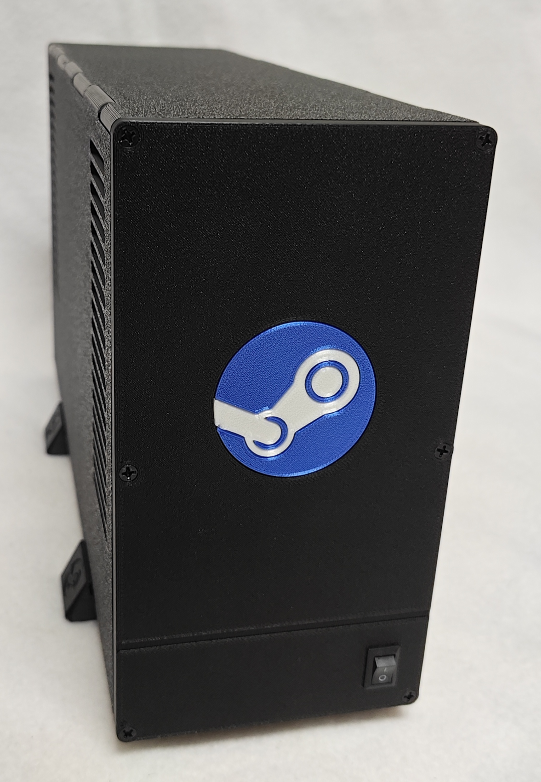 Step 13. Start gaming! |
Copyright © 2026 Pocket Adventures.com